High power drive systems for electric motors are a key component of industrial automation and robotic systems as they account for more than half of electrical energy consumed. Such drive systems have a central function in achieving energy savings.
The increasing pace of automation places the motor drive system at the heart of the future industry. Increased efficiency and reliability at higher powers will continue to be a focus of industrial drive solutions.
The benefits of inverterized motor drives include::
• Better efficiency when running at full speed
• Further efficiency gains as they can run at lower speeds when required
There are different ways to partition a motor drive system. Intelligent power modules (IPMs) include the inverter and internal drivers in a single module. Power integrated modules include the inverter converter and brake circuits, usually without drivers. The reason for this is that for three-phase AC input applications, intelligent power modules become very large.
Let’s have a look at a module without drivers:
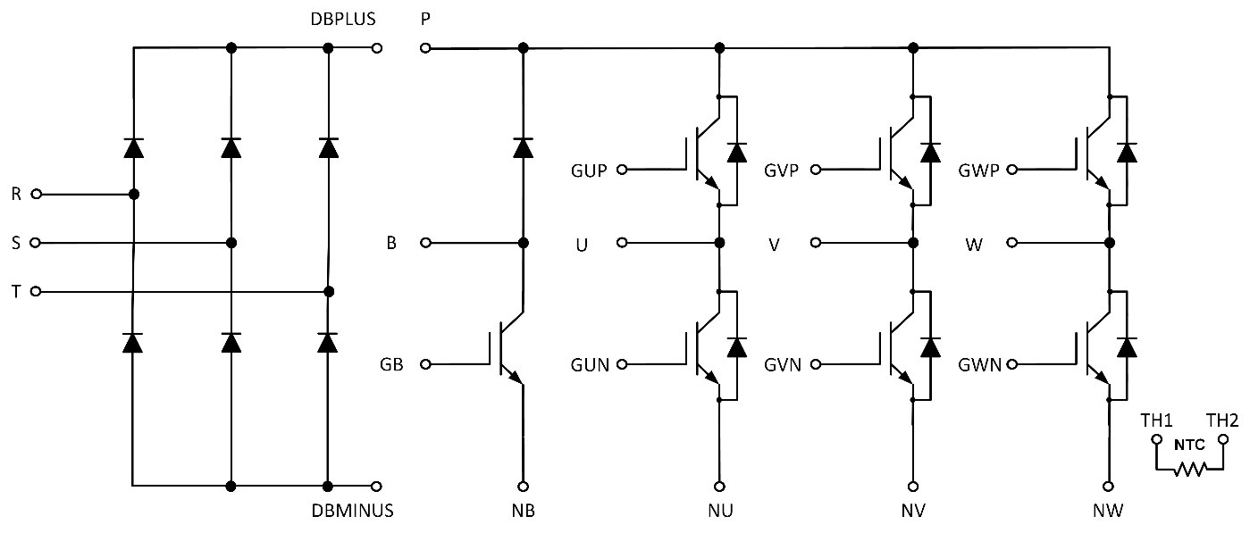
The pins of the module need to be spaced a certain distance apart from each other for
• Safety
• Long term reliability
These distances must be calculated for each application based on factors such as the maximum operating altitude of the drive, the effective voltages in the system, the isolation used in the system, pollution degree and CTI of the module and printed circuit board.
The detailed calculation for a typical motor drive application comes up with a minimum module dimension of around 70mm. Adding the spaces for the gate drive control pins makes the minimum module dimension even larger.
For low power industrial three-phase AC input applications, both IPM modules and gel-filled modules are extensively used: the IPM module not having the rectifier, and the gel-filled modules not having the driver. The trend for new designs is to use soldered pins for both gel-filled and IPM modules driven by the more widespread availability of robot soldering equipment.
Here is the cross-section of the new TMPIM (transfer-molded PIM) module. Note that the scale is stretched for illustration.
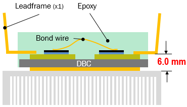
There is one clear advantage of TMPIM over existing modules. The overall module thickness is 8mm. The gap between the top of the pin and the top of the heatsink is 6mm, which is greater than the 5.5mm clearance required. Gel-filled modules also meet this requirement but they are a lot thicker (12mm versus 8mm for TMPIM). IPM modules are thinner. As a result, the mechanical designer needs to shape the heatsink adding extra manufacturing cost.
The IGBTs used in the TMPIM are robust Field Stop II 1200V IGBTs with short circuit rating of more than 10us at 150C, 900V bus voltage and 15V gate drive. Before release, the modules were extensively tested in motor drive tests, including bench tests. The NCD57000 isolated gate driver is ideal for driving the TMPIM. Six isolated drivers are used for each TMPIM. The NCP57000 gate driver has a DESAT function that detects an overload current and then performs a soft shutdown of the IGBT to prevent excessive voltage spikes from too fast turn off in short circuit conditions.
The TMPIM family can achieve well over 1000 thermal cycles. Standard gel-filled modules without any heat sink can typically achieve only 200 thermal cycles. Power cycle curves for the modules show excellent power cycling capability, dependent on the change in junction temperature. For higher power modules in the TMPIM, a high-performance aluminum oxide substrate is used. The lower thermal resistance results in lower thermal change resulting in higher power cycling capability when reading off the power cycling curve.
The current TMPIM includes 1200V CIB modules rated at 25A, 35A, 35A with a high-performance substrate and 50A with the high-performance substrate. New designs in the series will cover 650V CIB modules, 650V six-packs, 1200V six-packs and 650V modules with interleaved PFC and six-pack.