Industry’s First Intelligent Mixed Signal Bridgeless Totem-Pole PFC Controller Solves the AC-DC Power Supply Efficiency Challenge
Much of the power consumed in the world is supplied to some form of AC-DC power supply unit (PSU), meaning that their efficiency is important in terms of the cost of operation as well as emissions that affect the environment. At its simplest level, efficiency is the ratio of power drawn from the grid to the useful power supplied to the load. However, if the line current and voltage are out-of-phase or have different waveforms then the apparent power drawn can be significantly higher, dramatically reducing efficiency.

The ration between in-phase and out-of-phase operation is known as the power factor and a key goal for PSU designers is to ensure that this ratio is as close to unity as possible. In fact, this is sufficiently important that it is now mandated by legislation and standards such as IEC 61000-3-2 that places limits on the power in line harmonics.
Additionally, new efficiency standards stipulate efficiency levels across a wider range of operating power. For example, the 80 PLUS® program promotes 80% efficiency, at efficiency between 20% and 100% loading, while the highest level (known as ‘80+ Titanium standard’) specifies minimum efficiency of 90% at 10% loading and 94 % efficiency at 100 % loading.

80 PLUS® program Efficiency Level Certification
Source: CLEAResult®
Normally, the power factor is corrected by boosting the input mains to a DC level higher than the mains peak and then rectifying this to the output level using techniques such as pulse width modulation (PWM) which also forces the line current and voltage into alignment.
While this works well, inherent losses in the PFC stage (2% in boost DC-DC, 2% in bridge rectifier at low line) make achieving the 96% (230VAC input, 50% load) for the whole AC-DC power supply unit required by 80+ Titanium almost impossible.
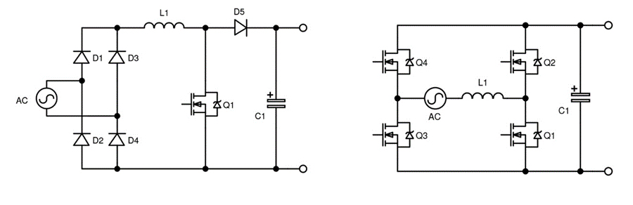
Traditional (left) and bridgeless Totem Pole (right) boost PFC circuits
Using a bridgeless design (known as Totem Pole PFC), the input line bridge diodes are replaced by a more efficient synchronous rectifier and the position of boost inductor rearranging to dramatically reduce loss. While this gives a theoretical 100% efficiency, non-ideal inductors and active switches conduction and switching losses mean this will not be achieved in practice.
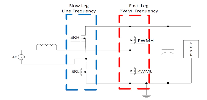
Totem Pole PFC Architecture
Approaches such as Continuous Conduction Mode (CCM) and Discontinuous Conduction Mode (DCM) have limitations at high and low power levels, so Critical Conduction Mode (CrM) is often used at powers up to a few hundred watts. Here, varied switching frequency forces operation on the border between CCM and DCM as load current or line voltage fluctuates giving a low turn-on loss while limiting the peak current to give acceptable conduction and core loss.
CrM’s variable switching frequency means that higher frequencies occur at light load, increasing switching losses that degrade efficiency- a real problem with meeting standby or no-load energy consumption limits mandated by standards for computing PSU. However, this can be addressed by clamping / ‘folding-back’ the switching frequency, thereby forcing DCM operation at light loads.
The TPPFC arrangement allows the ultimate PFC efficiency to be achieved although design can be a challenge with the need to control four active switching devices, detect zero current to force CrM, regulate the output and provide overcurrent and overvoltage protection. Digital controller that requires software coding is previously used to realize the topology and this further adds to the challenge, especially for less familiar or less experienced power supply designers.
To address these challenges, onsemi offers their NCP1680 - the industry’s first mixed-signal CrM totem pole controller. The device has a novel low-loss current sensing architecture and proven control algorithms for a cost-effective, high-performance and quick time to market solution. Therefore, just a few simple components are required externally to realize a full-featured totem-pole PFC, thereby saving space and component cost. Further, the cycle-by-cycle current limit is realized without the need for an expensive Hall Effect sensor.
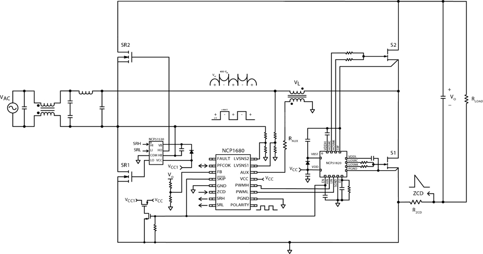
Typical Application Diagram for Totem Pole PFC using NCP1680
An evaluation board that provides 300 W at 395 VDC from 90-265 VAC line is available. This uses GaN HEMT for the fast leg switches and Si-MOSFETs for the AC line synchronous rectifiers and shows 98% efficiency across the line voltage range, down to 20% load.
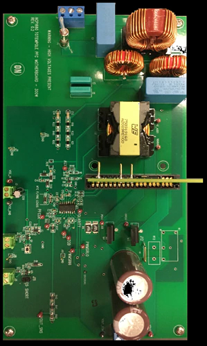
The NCP1680 evaluation board
Adoption of the totem pole architecture has been largely driven by adoption of Silicon Carbide (SiC) and Gallium Nitride (GaN) devices because of their advantages (mainly low reverse-recovery charge) when used in the fast leg of the totem pole. The NCP1680 can accommodate any switch type whether it is silicon based super junction silicon MOSFETs or SiC or GaN devices.